
Summary
This paper presents a methodology for the efficient upgrade of the maintenance strategies for all assets in existing facilities from initial asset confirmation to upload of the master data in the management system. The techniques are presented utilising a case study of a coal-fired power-station in Southeast Asia. The challenges which were addressed included an inaccurate plant configuration and inefficient preventive maintenance (PM) procedures resulting in a steady decline in the power-station reliability.
The approach commences by resetting the plant configuration by excising retired assets, adding assets which had not been registered and resetting all assets into an appropriate sense of hierarchy. This was followed by a systematic procedure for asset criticality ranking.
The limited PM procedures which were in place were reviewed and additional procedures developed to ensure an optimised maintenance strategy for all maintainable assets. This strategy was formally designed to be compliant with statutory obligations. A systematic procedure for Failure Modes and Effect Analysis (FMEA) was employed on an as-needed basis for complex assets with low reliability such as coal pulverisers. The main purpose of the FMEA in this case was to advise improvement to in-service asset care. The last phase of the work involved establishing a resource balanced PM schedule covering all maintainable assets.
Keywords: Maintenance Management, Maintenance Scheduling, Reliability Engineering, Asset Criticality Analysis, FMEA

Introduction
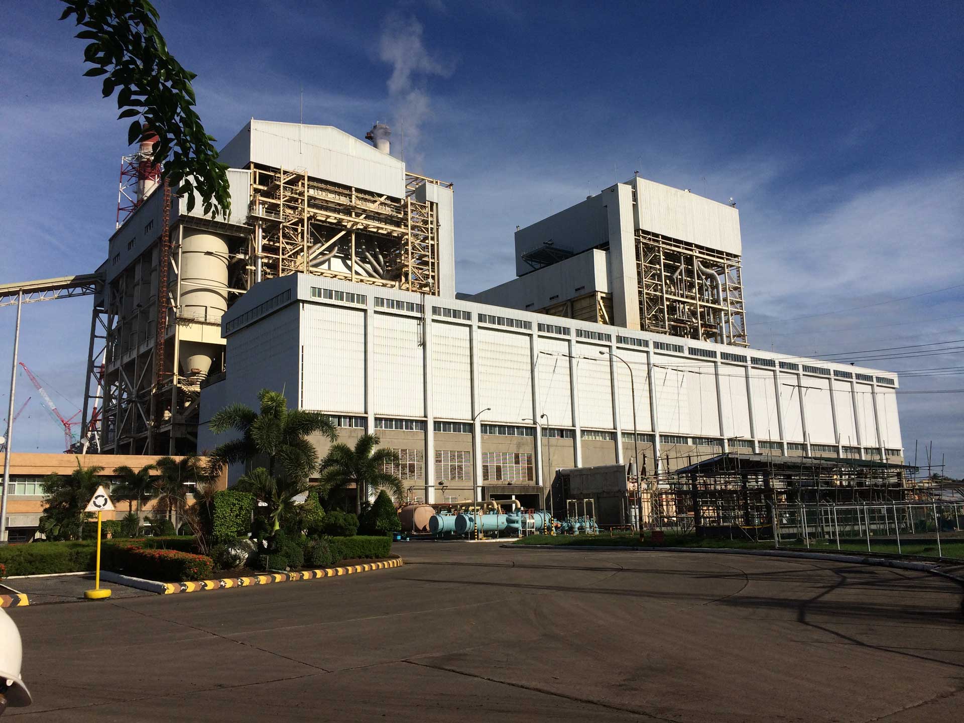
The subject coal-fired power station in Southeast Asia consist of two 300 MW units which were originally built by the government. The first unit was built and commissioned in 1980s. The second unit was built and commissioned in 1990s, which has different configuration compared to the first unit. In late 2009 the government sold the power station to a private company. In 2013 the new owners initiated a reliability analysis and an asset management (AM) review process.
The reliability analysis was carried out using the information from the power station’s CMMS data sets. This was done by analysing a data dump out of the CMMS data covering 20 months between September 2011 and April 2013. The purpose of the analysis was to identify the key reliability risks to the operation of the site. The reliability study focused on the critical areas of the power station which show excessive levels of reactive maintenance and hence were candidates for improvement, either through PM improvement, redesign or some modification.
The graph below shows the mean time between failures (MTBF) trend for the Unit 1 Coal Handling System. The MTBF is in days where values less than 1 infer multiple work orders per day. The reliability trend is displacing problems that do not appear to be improving.
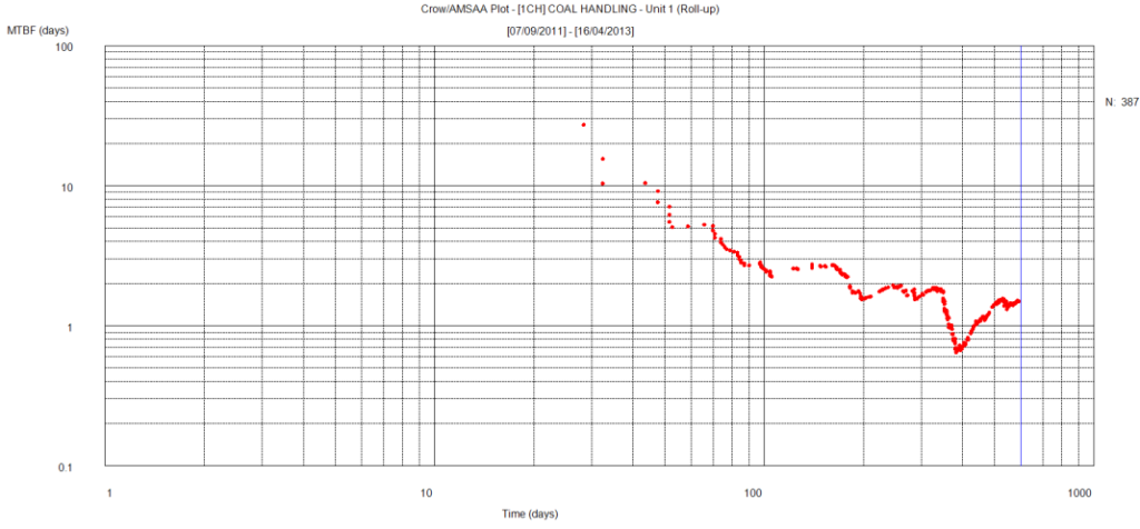
Figure 1: 1CH Coal Handling MTBF Trend [1]
The AM review was based on the PAS 55:2008 specifications for an asset management system [2]. The aim was developing an action plan to improve the asset management practices across the power station. The study was completed in 2013 prior to the release of the international standard ISO 55000: 2014 Asset Management.
The methodology utilised in the AM review process aimed at identifying tangible performance improvement throughout the power station. The foundation elements include defining and communicating a clear strategy, aligning the organisation with asset management service delivery and the use of information to optimise decision making about investments in the AM improvements [3]. Reviewing the plant configuration and development of detailed PM procedures for assets in the configuration were among the proposed improvement actions [4].
Another key recommendation was to confirm the compliant with the statutory obligations by reviewing all current PM tactics, amend as required, and create new PMs if necessary. The need was identified to ensure that power station is compliant with applicable standards, codes of practice, and other compliance mandates to ensure management confidence and risk minimisation [4].
The first phase of the project included asset list validation and development of asset hierarchy. This was followed by a systematic procedure for asset criticality ranking, consistent with international standards and utilising the power station’s risk and control matrix. Following the confirmation of the asset base and its classification for asset types, the limited PM procedures which were in place were reviewed to ensure the currency of PM procedures. The last phase of the technical work involved resetting the PM schedule to ensure the schedule is balanced for resources and to ensure the maximum possible operation of the plant with avoidance of unnecessary planned downtime.
Unique aspects of this work as reported in the case study included the speed and detail of the work, the end-to-end process being based as a repeatable and documented process, and the delivery of comprehensive technical documentation generated by software which managed all information from configuration through procedures to the schedule.
In addition to this work the power station management decided to upgrade the computerised maintenance management system (CMMS). As a result a number of considerations were taken into account:
- Codification of the equipment naming structure may need to be modified – the introduction of a new system may represent an opportunity to change how master data is coded;
- The master data has to be extracted from the original CMMS and made ready for load up into the new CMMS – very often the systems projects associated with the new CMMS are not sufficiently strong in this regard, leaving a legacy of incomplete data and lost information;
- The handling of PM task lists may differ between the systems, ie how the task items are listed on the work orders or how linked documents are managed. This is a system design issue and it was essential to understand the differences in the method by which the PM schedule is controlled and suppression of related job plans are achieved.
The work associated with upgrading the maintenance strategies and handling a change in the CMMS is shown in Figure 2.
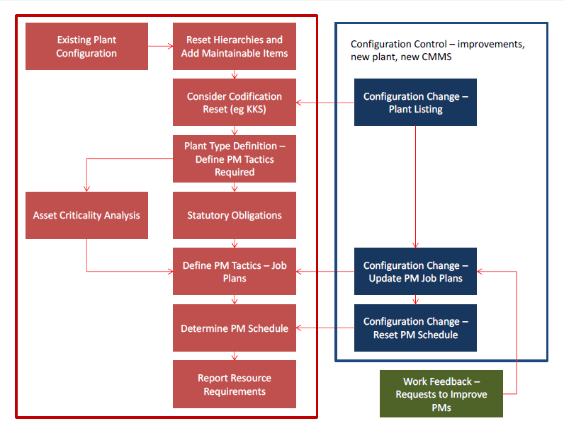
Figure 2: Overall Project Process
Asset Configuration
The establishment of an accurate asset hierarchy is the first step in development of an effective preventive maintenance which identify what needs to be maintained.
The original plant configuration of the power station did not have a strong sense of hierarchy. The parent children relationship between the assets were not established. The only grouping of the about 36000 listed assets were the unit and the system. For example 515 assets were identified to be part of the Fuel Coal System of Unit 1. The first objective of the project was to reset the configuration and introduce an appropriate sense of hierarchy such that:
- It is easy to locate equipment in the complex asset base
- Work results such as costs for equipment can be rolled up to parent levels for reporting purposes
- Work can be allocated to the maintainable item so that the life cycle costs of assets can be determined
- PMs will be set at the right level in the hierarchy to facilitate good schedule control which translates to efficient use of the labour resources
The project also allowed for the opportunity of ensuring compliance with the numbering system. The asset numbering system is a logical codification system for grouping the assets by functional area within the process while at the same time utilising type classification. Various plant numbering standards are used throughout the world. The “Kraftwerk-Kennzeichen-System (KKS)” Power Plant Classification System is one of these systems which were investigated. These systems allow good identification of assets by tracking them throughout the process. With the introduction of the parent hierarchy records, the current power station numbering system was compatible with KKS. The numbering system of the power station was not modified because all the drawings and documentation were based on the numbering system.
The information required for the asset hierarchy validation to ensure the accuracy and compliance with the numbering system are:
- The current CMMS asset hierarchy
- Assets lists not included in the CMMS (List of Electrical Switchboards, …)
- A set of Piping and Instrumentation Diagrams (P&ID’s) and a set of Single Line Diagrams (SLD)
- A set of latest inspection reports provided by the site maintenance contractors.
- Fire protection equipment essential services testing reports
- Maintenance reports for Thermostatic Mixing Valves, Backflow Prevention Devices
It was also required to ensure site personnel availability to assist in the plant walk around for validating the asset lists.
Resetting the original asset list with about 36000 records removed about 6000 assets from the asset list. These assets were either retired or duplicate records which people added over years to the asset list when they had problem finding a record in a flat hierarchy. About 1000 records were added to the asset list. Majority of these records were hierarchy assets to reset all assets into an appropriate sense of hierarchy. The remaining new records were for adding assets which had not been registered.
Cluster Maps
The first task in resetting the plant configuration is mapping the equipment and identifying the relationships between the assets to be maintained. The level of detail that is necessary for adequate maintenance systems design is quite extensive. This is often a major problem to the improvement team given the poor state of documentation and local knowledge regarding some machines, despite their criticality to the process. The cluster maps are an important technique for the team to understand the scope of a machine/process and its maintenance requirements. The following conventions are used with the cluster maps:
- Each entity warrants consideration for preventative maintenance.
- Where two entities are joined by an arrow the parent child relationship is in the direction of the arrow. They may also be serviced by two different PM tasks.
- Where two or more entities are grouped together, then all the assets are at the same level in the hierarchy
- The cluster may be serviced by the one PM task (albeit separate out electrical and mechanical tasks).
- Where the entity is shaded the reader will note a next level asset breakdown is provided.
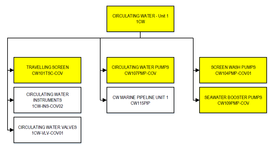
Figure 3: Unit 1 Circulating Water
Asset Criticality Assessment
Asset Criticality Analysis (ACA) is a systematic procedure for the analysis of a system of assets. The aim is to identify the consequence and likelihood of failure of an asset to perform its function, for the application of AM processes such as development of appropriate maintenance strategies.
The analysis may be performed at any stage in the life cycle of the assets. This analysis can be initiated as soon as the system is defined enough to be presented as a functional block diagram where performance of its included assets can be defined.
Application of ACA is preceded by a hierarchical deconstruction of the system into its component assets. In this case assets may refer to physical plant, control systems, software and the like. It is useful to employ simple block diagrams to illustrate this decomposition [5]. A simpler alternative for the management of large systems is a treeview where parent items can be broken out into branches of children items.
The analysis starts with choosing the appropriate lowest level of elements. This will generally be at proactively maintainable asset level, typically the level at which proactive actions will be applied.
A number of outcomes are sought:
- A consistent ranking of the significance of the assets delivering and supporting the business objectives of the power station.
- Rankings which allow prioritisation of subsequent analysis, for example FMEA.
- Banding of ranking scores to define minimum maintenance strategies and condition monitoring.
- Identification of “Classified” plant and reference for each asset
A consistent procedure for the performance of Asset Criticality Analysis was established for the power station [6] based on the AS/NZS ISO 31000:2009, Risk management – Principles and guidelines [7] and NORSOK Standard Z-008 [8].
Asset criticality ranking has multiple benefits:
- In the first instance it will identify where a conservative approach to the maintenance strategy is necessary to observe safety or manage down risk, and it will specify where the cost of the PMs can be relaxed since the risks being managed are not high;
- The results govern the level of surveillance from in situ condition monitoring, to routine condition monitoring to simple inspections. Asset criticality will govern what condition data needs to be managed over the longer term and will feed 5 and 10 year capital plans; and
- The results will be used in reliability reporting to advise on risk. A solution being implemented in a power station looks like the following:
- High risk issues on high criticality plant must be addressed immediately and they need to be expedited to senior executive. The power station leadership has to explain why they allowed these issues to develop;
- Low risk issues on high criticality plant must be reviewed by the power station management who will show judgement on what level of risk they tolerate – this is a trade-off between budget and risk;
- High risk issues on low criticality plant represent high priority maintenance which will be scheduled to be done and represents business as usual; and
- Low risk issues on low criticality plant need to be monitored and intervention is only justified when budget allows or to avoid growth in the risk.
As can be seen, asset criticality is an important building block in right setting the maintenance strategy as a trade-off between the cost of work and managing risk.
The power station’s risk matrix as shown in Figure 4 in conjunction with the power station’s consequence criteria table and likelihood criteria table were used for the asset criticality analysis. The following elements form the assessment process identified equipment criticality scores and equipment criticality bands.
- Financial Loss – Operational (MW loss)
- Financial Loss – Capital
- Regulatory Risk (including Environmental)
- Reputational Risk
The above elements were combined to generate a risk score after each of the element has been assessed.
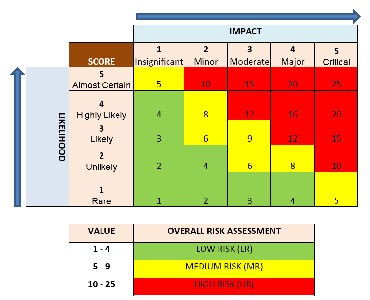
Figure 4: Risk Assessment Matrix [9]
Figure 5 shows the overall criticality analysis results for Unit 2 assets. Criticality was assigned to 98.6% of the Unit 2 assets. 199 assets (1.4%) were not classified during the asset criticality assessment. These assets are identified as “blank” in Figure 5. Note that the number of assets is a logarithmic scale to ensure that the small number of High Risk assets is not overlooked.
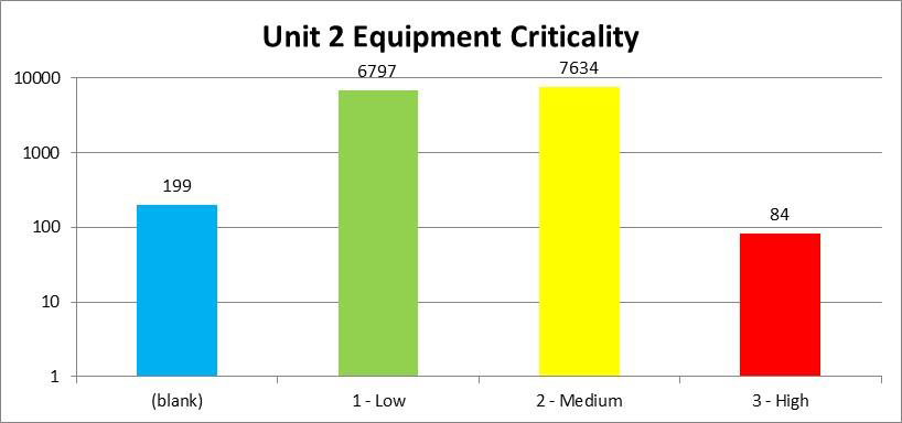
Figure 5: Unit 2 Criticality Profile
The overall criticality as shown above was used for uploading into the CMMS for work management purposes. The first category of asset criticality analysis, Financial Loss – Operational (MW loss), was equally important for the power station’s operators. Figure 6 shows the various categories of the operational financial loss impact from Unit 2 asset failures. It is important to note that the assets assessed as having Critical or Major impact on Financial Loss do not necessarily have high criticality ranking due to that the fact the failure rates (likelihood) of these assets are low (Rare of Unlikely to fail).
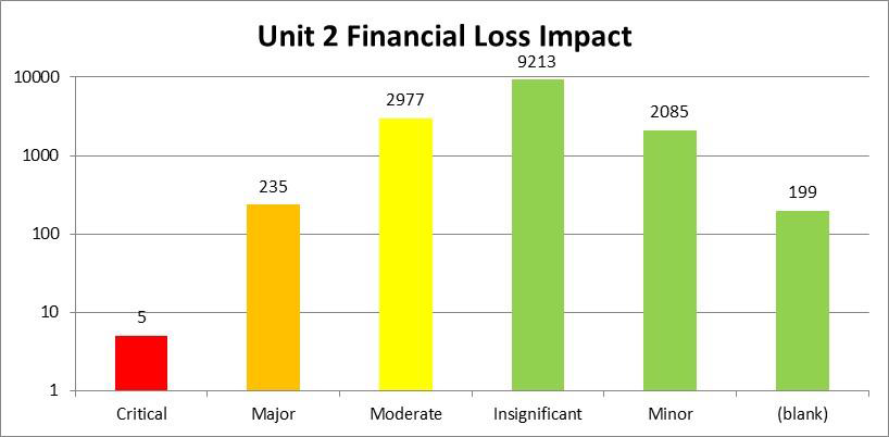
Figure 6: Unit 2 Financial Loss Impact
Maintenance Strategies and Procedures
This section is concerned with the identification and specification of maintenance strategies. These are PM procedures that specify a range of tasks (job plan) for a specific type of maintainable item. The maintenance strategy set will be consequently allocated to many incidents of the same type of equipment across the site. The relationship of maintenance strategies to procedures and routines is identified in Figure 7. PM procedures were derived from four sources:
- Existing power station PMs – respect the experience and what people have developed during the period of power station operation;
- Existing PMs developed over years for various maintainable items – a database of thousands of individual job plans which have been proven in multiple industries supported by a software designed for delivering quality PM strategies for bulk set of plants;
- Vendor PMs – these are found in manuals provided by the supplier of equipment. Our experience is that while the frequencies are conservative and can be modified, the content of the procedures are not conservative. They have been formed from design knowledge of the failure modes within the plant and are normally prudent; and
- Field developed PMs which require a formal FMEA process with the maintainers leading to the individual development of the PM procedure suitable for an unusual or rare kind of machine or system.
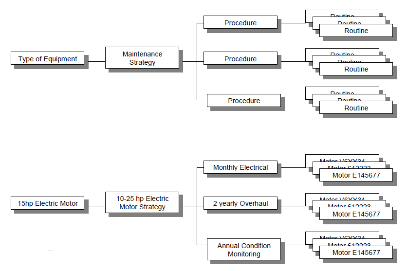
Figure 7: Maintenance Strategies [10]
All PM procedures were documented using the software for PM development which ensure a consistent format which complied with the power station asset management team requirements. All PMs were validated in a controlled process with members of the power station’s maintenance team in a process called Acceptance into Service. Acceptance means that the maintenance team certifies:
- The procedures are well written can be understood;
- The procedures are clear and can be simply implemented;
- The team believes the procedures are effective and necessary; and
- The team believes the nominated time and resources to do the work are valid.
This is a quality control process so each procedural sheet will be marked up with changes and signed off by the reviewing team member. An audit process cross checked that all agreed changes were present in the load-up files made ready for the CMMS. The maintenance team were accountable that they believe the strategy can be implemented. Prior to presenting the data to IT for load-up it was ensured the data is accurate and it is what has been agreed. Where the PM Job Plan required measurements to be undertaken, the procedure listed the measurements, their units and the tolerance limits for acceptable condition.
Table 1 lists the number of PM procedures and maintenance strategies developed by this project. It is important to note that due to the fact that two units have different asset configuration, condition and age, two sets of PMs were developed for the power station. All PMs follow the same format and consistent task description for similar tasks. For example the two sets of PMs for Unit 1 and Unit 2 Seawater Booster Pumps are similar with the exception of Unit 1 pump sets have direct drive but Unit 2 pump sets include a gearbox with additional tasks for gearbox maintenance.
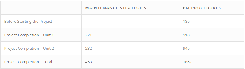
Table 1: List of PM Procedures and Strategies
Statutory Obligations
Statutory obligations are required under law where the operator has to meet specific conditions. These often in turn require the operator to meet regulations such as specified by standards or government departments.
A requirement for this project was to cross check the relevant Acts covering the operation of a power station and associated hazardous equipment in Southeast Asia. It was also investigated what ISO/ASTM standards must be met. It was considered that the power station’s senior executive will have a maintenance strategy signed off by the completion of this project as compliant, provided the included maintenance tactics are observed in full. This task was seen as a mandatory requirement for this work.
This work identified the governing regulations applicable to the maintenance of equipment at the power station. For example, Table 2 lists the applicable regulations and standards for the maintenance of Boilers identified by this work.
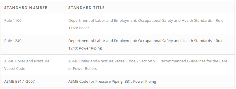
Table 2: List of Applicable Standards for Boilers
The purpose of the ASME Boiler and Pressure Vessel Code – Section VII: Recommended Guidelines for the Care of Power Boilers [11] is to promote safety in the use of power boilers. These guidelines are intended for use by those directly responsible for operating, maintaining, and inspecting power boilers.
Section C7 of the ASME Boiler and Pressure Vessel Code provides guidelines for making boiler repairs and alterations; recommended routine maintenance programs to improve boiler availability and keep power boilers in a safe operating condition.
ASME B31.1-2007 ASME Code for Pressure Piping: Power Piping [12] prescribes requirements for the design, materials, fabrication, erection, test, inspection, operation, and maintenance of piping systems. Piping as used in this Code includes pipe, flanges, bolting, gaskets, valves, relief devices, fittings, and the pressure containing portions of other piping components. Chapter VII of this code sets out requirements for the operation and maintenance of power piping.
All applicable standards were reviewed and the maintenance requirements for the applicable assets were identified. It was ensured the statutory obligations are fully met by the PM strategy. The individual procedures which contain the maintenance tasks required to satisfy the maintenance requirements of the above listed Standards were identified and documented. The list of statutory assets which the identified statutory maintenance strategies shall be applied to was also documented.
Failure Modes and Effect Analysis (FMEA)
One source of PM procedure development used for this project was a formal FMEA process with the maintainers and operators leading to the individual development of the PM procedure suitable for complex systems with low reliability.
FMEA is a systematic procedure for the analysis of a system of assets to identify the potential failure modes, their causes and effects on system performance (performance of the immediate assembly and the entire system or a process) within the scope of the analysis.
The analysis may be performed at one to two stages in the life cycle of the assets:
- Design FMEA – fundamental design information is reviewed to determine appropriate strategies for maintenance and in-service care.
- Maintenance & Operations FMEA – in-service data is reviewed within a FMEA framework to improve the in-service care to minimise forced downtime.
Application of FMEA is preceded by a hierarchical decomposition of the system into its component assets. In this case assets refer to physical plant. It is useful to employ simple block diagrams to illustrate this decomposition [5]. A simpler alternative for the management of large systems is a treeview where parent items can be broken out into branches of children items.
The analysis starts with choosing the appropriate lowest level of elements. A failure mode effect at a lower level may then become a failure cause of a failure mode of an item in the next higher level. The analysis proceeds in a bottom-up fashion until the end effect on the system is identified.
A number of outcomes are sought:
- Determination where compensating provisions inherently reduce the severity of a failure mode and thereby reduce the level of action required to control its occurrence
- Identification of the critical assets and those failure modes which have a strategic effect on the overall system or otherwise have consequences of significant severity
- Mitigating actions to either detect a failure mode in its infancy or to mitigate its propagation to the point of asset failure – these actions are the embryonic preventive maintenance strategy for the system
The FMEA objective was to improve reliability of the physical equipment or systems in the context of the maintenance and operations as shown in Figure 8
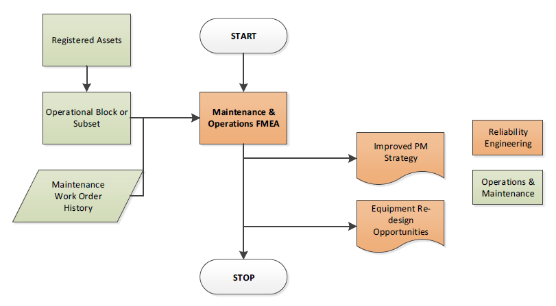
Figure 8: FMEA Process
The purpose of the Maintenance FMEA is to advise improvement to in-service asset care both through the preventive maintenance strategy and the approach to operator care. It may also advise on possible design opportunities where intractable loss of performance may be designed out with new equipment replacing existing plant and systems. A consistent procedure for the performance of FMEA was established for the use of reliability engineers at the power station [13]. The procedure set out in this case was fully compliant with the International Standard IEC 60812 for FMEA [14] and BS 5760: Part 5 for FMEA and FMECA [15].
FMEA – Coal Pulverisers and Associated Coal Feed System
The defined scope for the FMEA carried out during this project included the Unit 1 and Unit 2 Fuel Coal System consisting of coal bunker silos, coal feeders and coal pulverisers. The analysis covered all assets for Unit 1 and Unit 2 Fuel Coal System. The reasons for undertaking FMEA on Fuel Coal System (both Unit 1 & Unit 2) was to improve the reliability of FC System. During the period 1 January 2013 to 21 November 2013 the power station incurred a loss of 847 Hours due to Pulverisers and Coal Feeder trips. This excludes coal ‘Hang Ups’ in the coal silos due to bridging and only focuses on the mechanical, electrical & instrument failures for this period.
38 Failure modes were analysed for the above assets and 170 Failure Causes were identified. The current maintenance strategies were reviewed for adequacy to eliminate the failure causes or raise advanced notification for each failure mode. The current maintenance strategies addressed 6 out of 38 failure modes. 23 failure modes were partially addressed by the current strategies but reliability improvement can be realised from improved maintenance strategies. 9 failure modes were not addressed in the current maintenance strategies.
The findings from FMEA identified those failures which have unwanted effects on system operation and allow improvements of the system’s reliability and maintainability. The results were used during the review and formation of the revised detailed maintenance tasks for FC System.
PM Schedule and Resources Analysis
The PM schedule is the heart of the maintenance strategy. Within the CMMS it generates work orders which will direct specific resources to undertake specific PM Job Plans on specified equipment or using specified routes covering multiple equipment items. All steps within this case study on the maintenance strategy were directed to ensuring that the PM Schedule:
- Covers all plant to be maintained using a PM strategy;
- The right PM tactic is deployed to address known failure modes on the target equipment;
- Equipment is made available for PM work either in a running state (eg for condition monitoring) or stopped state (ie isolated);
- A schedule is available to provide monthly warning in advance of the work to be done so that resources and parts can be made available; and
- The right resources will be working on the right job.
A key analysis of the PM schedule is the statement of labour hours required for different craft types per week, and how much work is on running and non-running equipment. The work ensured the PM schedule is balanced for resources and provide maximum possible operation of the plant with avoidance of unnecessary planned downtime. Figure 9 shows an example of the labour hours required for the developed PMs. Some of the PM work may be allocated to shutdowns as standard work packs. In such case the scheduling of this work is to an outage period.
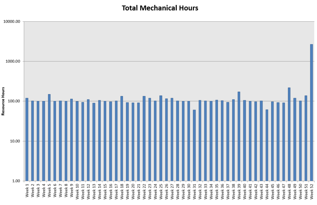
Figure 9: PM Schedule Mechanical Table
Conclusion
This paper presented a methodology for the efficient upgrade of the maintenance strategies for existing facilities with the aim of improving asset management practices. A comprehensive process from the initial asset validation to upload of the master data into a new computerized maintenance management system was employed. The techniques were presented utilising a case study of a coal-fired power-station in Southeast Asia. The power station had a maintenance management system which was installed for more than a decade but has been neglected and allowed to deteriorate to a level with little impact on plant reliability.
The challenges which were addressed included an inaccurate plant configuration, inefficient preventive maintenance procedures and scheduled work. The approach commenced by resetting the plant configuration by excising retired assets, adding assets which had not been registered and resetting all assets into an appropriate sense of hierarchy. This was followed by a systematic procedure for asset criticality ranking, consistent with international standards and utilising the power station’s risk and control matrix.
Following the confirmation of the asset base and its classification for asset types, the limited PM procedures which were in place were reviewed and additional procedures developed to ensure an optimised maintenance strategy for all maintainable assets. A systematic FMEA procedure, consistent with international standards, was employed on an as-needed basis for complex assets with low reliability such as coal pulverisers. The main purpose of the FMEA in this case was to advise improvement to in-service asset care.
This strategy was formally designed and confirmed to be compliant with statutory obligations. To ensure statutory compliance, the governing regulations applicable to the maintenance of equipment at the power station were identified. The applicable standards and regulations to all asset types at the power station were reviewed for maintenance requirements. For all statutory assets the individual procedures which contain the maintenance tasks required to satisfy the maintenance requirements of the applicable regulations were identified. A registry of the statutory assets identified the assets which the statutory maintenance procedure shall be applied.
The last phase of the technical work involved resetting the PM schedule, ensuring resource and access were balanced and all maintainable assets are maintained in as efficient manner as possible. Unique aspects of this work as reported in the case study included the speed and detail of the work, the end-to-end process being based as a repeatable and documented process, and the delivery of comprehensive technical documentation generated by the software which managed all information from configuration through procedures to the schedule.
The success of such work is based on actual PM work orders being generated from the maintenance management system, and hence one of the deliverables of this work was upload files for all data to the system in formats which were consistent with the application employed. Codification and specific format requirements had to be accommodated by the strategy design software so no manual adjustment of individual procedures was required.
The first work order based on the revised PM tasks and PM schedule was released in January 2015, which was a few months after the completion of the engineering work. The delay in the implementation of the engineering work was due to the delay in the commissioning of the new CMMS followed by a major shutdown of one of the units of the power station. It has been recommended to the management of the power station to initiate a follow up reliability analysis a few months after upgrading the maintenance management system. This analysis plus the trend in power generation will identify the extent of the power station’s reliability from the proposed changes.
Acknowledgements
This work has been funded by the subject power station of this study in Southeast Asia and various Australian organisations. The author acknowledges contributors from multiple organisations as well as his colleagues in Covaris.
References
[1] R A Platfoot, C Cunningham, Reliability Analysis of the CMMS Data, Unpublished Document for the subject power station in Southeast Asia, May 2013
[2] BSI PAS 55-2 2008 Asset Management
[3] R A Platfoot. “Integrating Asset Management with Work Delivery and Continuous Improvement”, 8th WCEAM Hong Kong, 2014.
[4] S Safi, P Milankovski, R Platfoot, Asset Management Audit, Unpublished Document for the subject power station in Southeast Asia, July 2013
[5] IEC 61078:2006, Analysis Techniques for Dependability – Reliability Block Diagram and Boolean Methods
[6] S. Safi, Asset Criticality Policy and Procedure, Unpublished Document for the subject power station in Southeast Asia, March 2014
[7] AS/NZS ISO 31000:2009, Risk management – Principles and guidelines
[8] NORSOK Standard Z-008 Rev2, Nov 2001
[9] Risk and Control Matrix of the subject power station in Southeast Asia
[10] S. Safi, S. Mozar, “From Reactive Maintenance to Proactive Preventive Maintenance System,” ICOMS-2004, Sydney, Australia
[11] ASME B&PVC VII (2010), Boiler and Pressure Vessel Code, Part VII, Recommended Guidelines for the Care of Power Boilers
[12] ASME B31.1-2007 ASME Code for Pressure Piping: Power Piping
[13] S. Safi, FMEA Policy and Procedure, Unpublished Document for the subject power station in Southeast Asia, January 2014.
[14] International Standard IEC 60812 – Analysis techniques for system reliability – Procedure for failure mode and effects analysis (FMEA) Second Edition 2006-01
[15] BS 5760: Part 5 (1991) – Reliability of systems, equipment and components Part 5: Guide to failure modes, effects and criticality analysis (FMEA and FMECA)